DIY Touch Sensor (Capacitive Sensor)

Capacitive Sensors is a technology which detects proximity or touch (by a hand/skin, or any conductive object). The sensor measures the capacitance between the input and output nodes to detect a touch. The sensor detects anything that is conductive, so these sensors can be used to replace any normal switches to make them touch sensitive or even be utilized in making touch screens for monitors, touch-pads and touch sensitive buttons in phones, laptops or other devices.  

About the Touch Sensor:
The sensor setup in the example below is a simple DIY setup without using a commercial sensor chip.

Setup:
Attach a high value resistor (1-10M Ohm) between an input and an output pin. Also connect a short bare copper or aluminum wire/foil to the input pin. If the wire is to be a longer one, make sure it isn't touching any other wires along the way, or just use a covered wire with a small uncovered area at its tip. This will be the touch sensor for the capacitive sensor (i.e. activates at touch).

An LED is also connected to a separate output pin and GND. This LED turns on when someone touches the sensor with a conductive object (e.g. capacitive sensors are most commonly used to sense touch with skin/fingers etc.)

It is also possible to vary the capacitance reading of this setup to detect even when one's hand is 3 to 4 inches from the sensor, or make it activate just on absolute touch. One can use lower values of R (e.g. 1 M Ohm or less) for absolute touch to activate the sensor. With a 10 M resistor the sensor should start to respond 1-2 inches away.

Code:
When the value at the output pin is changed from LOW to HIGH, it changes the state of input pin to LOW(or 0) for a very short time interval. This time interval is defined by:

T  =  R  x  C,

where
T  =  time interval,
R  =  resistance,
C  =  capacitance of the sensor + capacitance of any conductive object in contact with the sensor pin

So, this time interval increases if the sensor on input pin (the bare copper/aluminum wire) is touched with a conductive object. And the interval reduces again when the conductive
object is removed from the sensor.  So, we measure the length of the time interval to get a measure of capacitance on the touch sensor.

Threshold:
The value of the threshold here depends on how sensitive the user wants the sensor to be.  The lower bound of the threshold would be the value of R (the resistance) itself, since that remains constant in when measuring T = R x C. But, the upper bound can be changed depending on the requirements of the system.

Smoothing:
However, there might be a lot of jitter as well as environmental conditions that might make the
capacitance value jump around a lot. This can be overcome by using a smoothing function. For example, this can be done by reading the capacitance measure for a number of times and then averaging the values overall.

Circuit:

Schematic:
Sample Arduino Program:
About this Code:
When the output at pin4 transitions from LOW to HIGH, it changes the state of input pin5 to LOW(or 0) for a very short time interval. This time interval increases if the sensor on input pin5 is touched with a conductive object and vice versa.

At the start of each main loop cycle in this program, we set the value of a variable 'capX' to 0. Then for the time interval the value at input pin5 returns LOW, we increment 'capX'. This results in 'capX' being barely incremented if the sensor is not in contact with a conductive object. But, as soon as someone holds/touches the sensor the value of capX quickly increments because of the longer time interval. So, if the capX value is bigger than a given threshold, it means the sensor just detected a touch.

The value of the threshold here depends on how sensitive the user wants the sensor to be and/or the environmental affect the initial value at the sensor itself.

/*

This code turns the LED on while the sensor is in contact
with a conductive material (e.g. when someone touches it
with their bare skin/fingers)

Setup:
Attach a high value resistor (1-10M Ohm) between an output
pin 4 and input pin 5. Also connect a short bare copper or
aluminum wire/foil to the input pin5. Connect an LED to
output pin13 and GND.

By: Naureen Mahmood.

*/

#define LED        13
#define THRESHOLD   5

int capI;      // interval when sensor pin 5 returns LOW

void setup()
{
  Serial.begin(9600);
  pinMode(LED, OUTPUT);
  pinMode(4, OUTPUT);     // output pin
  pinMode(5, INPUT);      // input pin
}

void loop()
{
  capI = 0;      // clear out capacitance measure at each loop

  // transition output pin4 LOW-to-HIGH  to 'activate' sensor pin5
  digitalWrite(4, HIGH);     

  // On activation, value of pin 5 stays LOW for a time interval T = R*C.
  // C is big if the sensor is touched with a conductive object.
  // Increment capI for the interval while pin5 is LOW
  int val = digitalRead(5);  // read the input to be checked
  while (val != HIGH){   
    capI++;   
    val = digitalRead(5);    // re-read the input to be checked
  }
  delay(1);
 
  // transition output pin4 HIGH-to-LOW to 'deactivate' sensor pin5
  digitalWrite(4, LOW);     
  Serial.println(capI, DEC);  // print out interval

  if (capI > THRESHOLD)       // Turn LED on if capI is above threshold
    digitalWrite(LED, HIGH);
  else 
    digitalWrite(LED,  LOW);
}


Sample Arduino Code (with smoothing filter):

About this Code:
 This code uses the same technique for measuring capacitance as  the earlier one. But, this one also uses a smoothing filter to  remove any jitter along the measured values by averaging 4 consecutive values from the input pin. Then at each iteration of that 4-time loop, after transitioning the output pin 4 from low to hi, we measure the duration for which the value at input pin 5 remains low (and save it in variable capLo). Then we transition the output pin 4 back to low, and measure the duration for which the input pin 5 is high (and save it in variable capHi). We won't be using the capHi variable for the filter but, this helps read out any noise at the input pin before the next iteration.

After this loop, the smoothing filter is applied to the measured capLo value. We use the current capLo value and previous filtered value, called prevCapI, from the last iteration of the loop function (not the for-loop), and multiply them by f_val and (1 - f_val) respectively. Here f_val is the amount of filtering to be applied to the measured capacitance values. This value can be between 1 (no filter) and 0.001 (max filter). This makes sure both the current and previous values of the measured capacitance are included in the final filtered value, and the value f_val determines what proportion of each is to be included in the final value. Therefore, even the sudden changes in the capacitance are smoothed out based on previous input.

So, then the LED brightens or dims smoothly based on these filtered values from the touch sensor.

/*    

 This code makes the LED intensity go from dim to bright
 smoothly when someone touches the sensor with a bare
 finger, and then smoothly dims down to turn off after
 the person lets go of the sensor.

 Setup:
 Attach a high value resistor (1-10M Ohm) between output
 pin 4 and input pin 5. Also connect a short bare copper or
 aluminum wire/foil to the input pin5. Connect an LED to
 output pin 11 (or any PWM pin) and GND.

 [ Smoothing filter based on code by Paul Badger found at:
   http://www.arduino.cc/cgi-bin/yabb2/YaBB.pl?num=1171076259 ]

 By: Naureen Mahmood
 */

// You can change the bounding values for the capacitive/touch
// sensor depending on what values work best for your setup
// + environmental factors
#define LOW_T       10    // lower bound for touch sensor
#define HIGH_T      60    // upper bound for touch sensor
#define LED         11    // LED output pin

// These are variables for the low-pass (smoothing) filter.
float prev_capI;    // previous capacitance interval
float filt_capI;    // filtered capacitance interval
float f_val = .07;  // 1 = no filter, 0.001 = max filter
unsigned int capLo; // duration when sensor reads LOW
unsigned int capHi; // duration when sensor reads HIGH

void setup()
{
  Serial.begin(9600);

  pinMode(LED, OUTPUT);
  pinMode(4, OUTPUT);    // output pin
  pinMode(5, INPUT);     // input pin
}

void loop()
{  
  // clear out the capacitance time interval measures at start
  // of each loop iteration
  capHi = 0;
  capLo = 0;

  // average over 4 times to remove jitter
  for (int i=0; i < 4 ; i++ )
  {      
    // LOW-to-HIGH transition
    digitalWrite(4, HIGH);   

    // measure duration while the sense pin is not high
    while (digitalRead(5) != 1)
      capLo++;
    delay(1);

    //  HIGH-to-LOW transition
    digitalWrite(4, LOW);             

    // measure duration while the sense pin is high
    while(digitalRead(5) != 0 )    
     capHi++; 
    delay(1);
  }

  // Easy smoothing filter "f_val" determines amount of new data
  // in filt_capI
  filt_capI = (f_val * (float)capLo) + ((1-f_val) * prev_capI);   
  prev_capI = filt_capI; 

  Serial.println( filt_capI ); // Smoothed Low to High

  // Map the capacitance value range to LED brightness (0-255)
  int ledVal = map (filt_capI, LOW_T, HIGH_T, 0, 255);

  if (filt_capI > LOW_T)
    analogWrite(LED, ledVal);
  else
    analogWrite(LED, 0);
}

Heidi


The final version of the robot is the same as the earlier design of squarish-looking robot. But the colors are much brighter now. The robot has the following characteristics:

1. Range-finder detects if someone has come within 30 cm of the robot and if so, the robot abruptly wakes up, moving its head up and eyes lighting up. The robot's neck pulls up using a servo motor and its eyes have LED's which light up to show it's awake and ready to play.


2. Force Sensitive Resistors in the ears detect the slightest rub and if someone scratches one of its ears, the robot giggles (bobs its head and blinks eyes).


3. Capacitive Sensor in the nose detects if anyone touches the nose. If so, the robot pulls its head back down.


4. Wheels activate if a person messes with the robot's nose too much. The robot moves it's head down and then suddenly rolls away to a side (moves to left or right alternately).


The final breadboard looked somewhat like this: (there are still a few connections missing - which I can't take a picture of since the breadboard is inserted into the robot-body to connect to those).


==========================================

Arduino Code:

#include [servo.h]

#define EYES_OPEN  255
#define EYES_SHUT  0
#define EYES_DIM   30

#define HEAD_HI    10
#define HEAD_LO    100

#define RANGE_NEAR 35
#define RANGE_NEARER 20
#define RANGE_FAR  100
#define R_SAMPLES  20
#define INTERVAL   10000
#define WHEEL_INTERVAL   1000

#define TOUCH_HI   60
#define FSR_HI     30

int HEAD = HEAD_LO;
int EYES = EYES_SHUT;

unsigned long currMillis;
long prevMillis = 0;
long prevWheelMillis = 0;
boolean dir = true;
boolean running = false;

// ##################
// ## Analog Pins: ##
// ##################

// RANGEFINDER VARs
int rangeSum=0;         //Create sum variable
int rangeCount = 0;
int rangePrev = RANGE_NEAR;
int rangeCurr = RANGE_FAR;

// FSR VARs
int FSRval1;
int FSRval2;

// ###################
// ## Digital Pins: ##
// ###################

// CAPACITATIVE SENSOR VARs
unsigned int touchX, touchY;
float touchSum, touchOut, touchVal = .07;    // these are variables for a simple low-pass (smoothing) filter - touchVal of 1 = no filter - .001 = max filter

// SERVO VARs
Servo myservo;  // create servo object to control a servo

int pinTest = 3;
int pinFSR1 = 0;
int pinFSR2 = 1;
int pinRange = 2;    // select the input pin for the ultrasonic sensor

const int pinTouchOut  = 2;
const int pinTouchIn   = 3;
const int pinTouchGrd  = 4;
const int pinServo     = 5;
const int pinEyes      = 6;

const int motor1Pin = 9;    // H-bridge leg 1 (pin 2, 1A)
const int motor2Pin = 8;    // H-bridge leg 2 (pin 7, 2A)
const int motor3Pin = 11;    // H-bridge leg 1 (pin 2, 1A)
const int motor4Pin = 12;    // H-bridge leg 2 (pin 7, 2A)
const int enablePin = 10;    // H-bridge enable

int runRangeFinder();
int runTouchSensor();
int runFSR();

int noseCount = 0;

void setup()
{
  Serial.begin(9600);

  pinMode(pinTest, OUTPUT);        // TEST LED
  pinMode(pinRange, INPUT);        // RANGEFINDER
  pinMode(pinFSR1, INPUT);          // FSR
  pinMode(pinFSR2, INPUT);          // FSR
 
  pinMode(pinEyes, OUTPUT);        // EYES' LEDs
  pinMode(pinTouchOut, OUTPUT);    // output pin
  pinMode(pinTouchIn,   INPUT);    // input pin
  pinMode(pinTouchGrd, OUTPUT);    // guard pin
  digitalWrite(pinTouchGrd, LOW);  // could also be HIGH - don't use this pin for changing output though
  myservo.attach(pinServo);        // SERVO:

  // set all the other pins you're using as outputs:
  pinMode(motor1Pin, OUTPUT);
  pinMode(motor2Pin, OUTPUT);
  pinMode(motor3Pin, OUTPUT);
  pinMode(motor4Pin, OUTPUT);
  pinMode(enablePin, OUTPUT);
}

void loop()
{
  currMillis = millis();
 
  randomSeed(analogRead(pinTouchGrd));  // setting the seed to data from unconnected pin
  runRangeFinder();
  runTouchSensor(); 
  runFSR();
  runWheels();

  // when normal --> return to Normal Position
  myservo.write(HEAD);                 
  analogWrite (pinEyes, EYES);
/*
  Serial.print("\t Touch: ");
  Serial.print( (long)touchOut, DEC); // Smoothed Low to High
  Serial.print("\t FSR: ");
  Serial.print( FSRval);
  Serial.println();
*/
  delay(10); 
}


//==================
//  RANGE FINDER
//==================
int runRangeFinder()
{
  unsigned long currRangeMillis = millis();
  // sampleCount starts life at 0, then loops through sampleSize
  rangeSum += analogRead(pinRange);
  rangeCount++;
  if (rangeCount == R_SAMPLES)
  {
    rangeCurr= rangeSum/R_SAMPLES;
  
    Serial.print("Range: ");
    Serial.print(rangeCurr);
    Serial.println();
    rangeCount = 0;  rangeSum = 0;
    if (rangeCurr <= RANGE_NEAR)
      rangePrev = RANGE_NEAR;
    if (currRangeMillis - prevMillis > INTERVAL )
    {
      prevMillis = currRangeMillis;
      if (rangeCurr >= RANGE_FAR)
        rangePrev = rangeCurr;
      Serial.print(" Interval - Curr: ");
      Serial.print(rangeCurr);
      Serial.print(" Prev: ");
      Serial.print(rangePrev);
      Serial.println();
    }
  }
 
  if (rangeCurr < RANGE_NEAR)
  {
    Serial.println("Hi there!");
//    talk();
    HEAD = ( HEAD > HEAD_HI ? HEAD-=10 : HEAD_HI);
    EYES = ( EYES < EYES_OPEN ? EYES+=10 : EYES_OPEN);
  }
  else if(rangePrev >= RANGE_FAR && rangeCurr >= RANGE_FAR)
  {
    HEAD = HEAD_LO;
    EYES = EYES_SHUT;
  }
 
  return 0;
}

//==================
//  TOUCH SENSOR:
//==================
int runTouchSensor()

  touchX = 0;        // clear out variables
  touchY = 0;

  for (int i=0; i < 4 ; i++ )
  { // do it four times to build up an average - not really neccessary but takes out some jitter

    digitalWrite(pinTouchOut, HIGH);     // LOW-to-HIGH transition
    while (digitalRead(pinTouchIn) != 1) touchX++;// while the sense pin is not high
    delay(1);
    digitalWrite(pinTouchOut, LOW);      //  HIGH-to-LOW transition
    while(digitalRead(pinTouchIn) != 0 ) touchY++; 
    delay(1);
  }

  touchOut =  (touchVal * (float)touchX) + ((1-touchVal) * touchSum);  // Easy smoothing filter "touchVal" determines amount of new data in touchOut
  touchSum = touchOut;

//  Serial.print(touchOut);
//  Serial.println(touchOut);
 
  // when nose touched --> hide
  if (touchOut >= TOUCH_HI)
  {
    Serial.println ("You touched my Nose! :(");
//    EYES = EYES_DIM;
//    HEAD = HEAD_LO;   

    myservo.write(HEAD_LO);                 
    analogWrite (pinEyes, EYES_DIM);
    noseCount += 1;
    Serial.print(" NoseCount: ");
    Serial.println(noseCount);
    delay (1000);
    }
  return 0;
}

//==================
//  FORCE SENSOR:
//==================
int runFSR()
{
  FSRval1 =  analogRead(pinFSR1);
  FSRval2 =  analogRead(pinFSR2);
 
  //  when ear rubbed --> laugh
  if (FSRval1 >= FSR_HI || FSRval2 >= FSR_HI)
  {
    Serial.println("Hehehe :D");
    for (int i = 0; i < random(2,5); i++)
    {
      myservo.write(HEAD_HI);                 
      analogWrite (pinEyes, EYES_OPEN);
      delay(100);

      myservo.write(HEAD_LO);                 
      analogWrite (pinEyes, EYES_DIM);
      delay(130); 
    }
  } 
//  Serial.print(", FSR1: ");
//  Serial.print( FSRval1);
//  Serial.print(", FSR2: ");
//  Serial.println( FSRval2);
 
//  delay (500);
  return 0;
}

int runWheels()
{
    if (noseCount == 3 || running)
    {       
      if (currMillis - prevWheelMillis > WHEEL_INTERVAL )
      {
        prevWheelMillis = millis();
        if (!running)
        {
          digitalWrite(enablePin, HIGH);
          Serial.println("go!");
          running = !running;
        }
        else
        {
          Serial.println("stop!");
          digitalWrite(enablePin, LOW);
          noseCount = 0;
          running = !running;
          return 1;
         }
       
        if (dir)
        {
          Serial.println("dir1!");
          digitalWrite(motor1Pin, LOW);   // set leg 1 of the H-bridge low
          digitalWrite(motor2Pin, HIGH);  // set leg 2 of the H-bridge high
         
          digitalWrite(motor3Pin, LOW);   // set leg 1 of the H-bridge low
          digitalWrite(motor4Pin, HIGH);  // set leg 2 of the H-bridge high
         
          dir = !dir;
        }
        else
        {
          Serial.println("dir2!");
          digitalWrite(motor1Pin, HIGH);   // set leg 1 of the H-bridge low
          digitalWrite(motor2Pin, LOW);  // set leg 2 of the H-bridge high
         
          digitalWrite(motor3Pin, HIGH);   // set leg 1 of the H-bridge low
          digitalWrite(motor4Pin, LOW);  // set leg 2 of the H-bridge high
         
          dir = !dir;
        }
      }
    }
    return 0;
}
So far:


Wheels also move and eyes light up - still need to solder the wires so it can work when the body is mounted on top. The wheels' movement is dependent on signal from the range-sensor. It's still kinda iffy.

The nose has a home-made capacitive sensor, made with a high resistor to accumulate and respond to current (the real capacitive sensor i got from the Prof. Galanter was too big, bulky to be able to fit it easily inside the robot's head. The robot doesn't like it's nose being touched. hides away when nose is touched.

Head bobs and eyes blink if the ears are rubbed (FSR's inside the ears).

Proj 3: Bug

Projects using 3 sensors & two motors:

The object is a small mechanical flying insect called 'Bug'. The bug follows any motion detected in the dark. It either goes around following the motion quietly or, if a certain pressure sensor hasn't been pressed, bug follows the motion while sounding off an alarm. So it can serve as an intruder detector or, in the motion is not caused by an intruder, the insect simply follows the person moving about, casting light on them, knocking into them and hence, 'bugging' them.. =)

It has three sensors:
  • Light sensor
  • A direction sensing motion detector
  • Pressure sensor

And two motors are:
  • DC motor
  • Servo


Model:
The bug has a set of propellers at the front, which are controlled by the DC motor. And it has a flap at the back which can swing 180 degrees using the servo, to allow the insect to turn while in flight.

The insect becomes active only in the dark. As soon as the insect detects any motion in the dark, it starts flying towards it while sounding off a low alarm. The alarm sound can be turned off by pressing onto a hidden pressure sensor on the bug or else it would keep increasing in intensity with each passing minute.

Mechanism:
The bug remains inactive until the light sensor detects there isn't enough light in the room / surroundings. It's green LED lights turn up to indicate that it is 'awake' and detecting motion around it.

As soon as the motion detector detects any motion, the bug starts flight. The DC motor turns on to lift the insect off the ground and the direction sensing motion detector can relay which direction the tail-flap should turn. At the same time the alarm sounds off as well.

When someone pushes onto the pressure sensor, the alarm sounds off but, the bug continues flying and following the motion direction. If the motion sensors stop receiving input for over 30 seconds, the bug circles around it's surroundings for another 30 seconds. If no further motion is detected and the alarm is off, the bug slowly settles down and returns to its initial 'awake' position, waiting for another input from the motion sensors.


Concept Design:
The initial concept design I had in mind for this project was something I had made with just .. junk .. from around my apartment some time ago. Here's what that rather not-so-good-looking bug looked like:


So, the idea for this project is mainly a flying bug - that looks somewhat like the dragonfly above. Possibly, even made to be not-so-pretty-looking 'on purpose' (to make it look like it was actually made out of junk found lying around). Just add a  propeller on the front, and a servo with a flap at the back  :) 

Simulation:
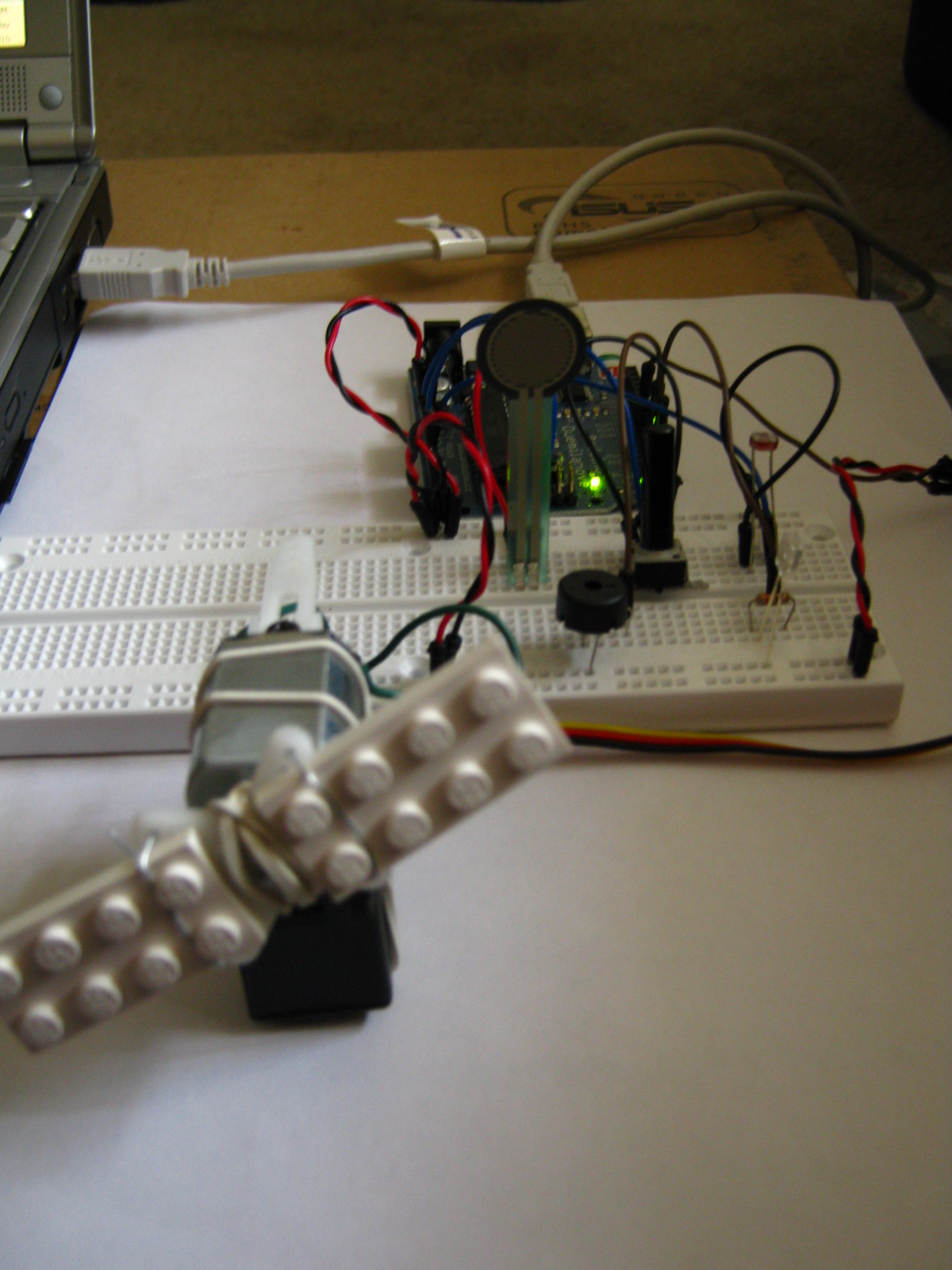
Here's a test simulation I worked on. The servo and the DC motor are connected together. The DC-motor has a couple of lego blocks attached to it as wings. The rest of the things, sensors, LED and buzzer are attached on the breadboard. Also, since we didn't have any direction sensing motion detectors, I have used a potentiometer to tell the servo which direction to move, assuming the moment the servo is first activated, is when motion is first detected. Moreover, the DC-motor already fried my earlier Arduino board because I forgot to attach it through a transistor - so, for now I have just left it off of the Arduino and connected it to an external power without any connection to the Arduino at all, ..just to be on the safe side! :\


p.s. the lego fan *did* really fly away at the end  of that clip!  :\

Proj 2: Accelerometer + Potentiometer driven Animation

2D motion of an animated dragonfly is controlled on screen by using input from an accelerometer.


The potentiometer knob can be used to turn up the opacity of a small radius around the dragonfly to display a hidden image underneath. Only the small area of the hidden image surrounding the dragonfly is visible at a time. You can move the dragonfly around with the accelerometer to explore different areas of the image.

p.s. (the potentiometer is actually meant to be a pressure sensor but, the potentiometer worked better for testing purposes)


** My Arduino Code **

/*
  Reading Accelerometer & Pressure Sensor
  Language: Arduino/Wiring
 
  Reads 3 inputs attached to analog input pins 0 - 3 of the Arduino.
  The first two can be the accelerometer X & Y, and the third a
  potentiometer, or a pressure sensor.
 
*/

int accl_x = 0;
int accl_y = 1;
int sensor = 2;

void setup()

  Serial.begin(9600);      // initialize the serial port:
}

void loop()
{
  int sensorReading;
 
  // read accelerometer X value
  sensorReading = analogRead(accl_x);   
  sensorReading *=    10;
  Serial.print(sensorReading, DEC);    // print its value out as an ASCII numeric string
 
  // print a comma after the last sensor
  Serial.print(",");
 
  // read accelerometer Y value
  sensorReading = analogRead(accl_y);   
  sensorReading *=    10;
  Serial.print(sensorReading, DEC);    // print its value out as an ASCII numeric string
 
  // print a comma after the last sensor
  Serial.print(",");
 
  // read sensor
  sensorReading = analogRead(sensor);   
  Serial.print(sensorReading, DEC);    // print its value out as an ASCII numeric string

 
  // after all the sensors have been read,
  // print a newline and carriage return
  Serial.println();
  delay (100);
}

** My Processing Code **
/*
  Accelerometer  
  Language: Processing

  This sketch takes ASCII values from the serial port
  at 9600 bps and maps them to screen coordinates.
  The values should be comma-delimited, with a newline
  at the end of every set of values.
  The expected range of the values is between 0 and 1023.

  Created 08 March 2010
*/

import processing.serial.*;
Serial myPort;                    // The serial port

PImage bg_img, mask_img;

Animation animation;
float xpos, ypos, oldx, oldy;
float sensor;
float drag = 30.0;

int maxNumberOfSensors = 3;

void setup ()
{
  // set up the window, background, framerate, and #of frames
  size(500, 500);      
  background(0, 0, 20);
  bg_img = loadImage("background.png");   // Loading background image
  mask_img = loadImage("mask.png");   // Loading background image
  animation = new Animation("dragonfly_", 16);
  frameRate(24);
 
  // List all the available serial ports:
  println(Serial.list());
  // Opening port 8 (my COM port talking to the arduino)
  String portName = Serial.list()[1];
  myPort = new Serial(this, portName, 9600);
  myPort.clear();
  // don't generate a serialEvent() until you get a newline (\n) byte:
  myPort.bufferUntil('\n');
  
  xpos = oldx = width/2;
  ypos = oldy = height/2;
}

void draw ()
{
  // Display the sprite at the position xpos, ypos
    tint (sensor, 255);    // setting the opacity of background
    image(bg_img, 0, 0);
    image(mask_img, xpos-(animation.getWidth()*4)+35, ypos-(animation.getHeight()*4)-70);

    tint (255, 255);      //  opacity of sprite always FULL
    animation.display(xpos-animation.getWidth()/2, ypos);
}

void serialEvent (Serial myPort)

  // get the ASCII string:
  String inString = myPort.readStringUntil('\n');

  // if it's not empty:
  if (inString != null)
  {
    // trim off any whitespace:
    inString = trim(inString);

    // convert to an array of ints:
    int incomingValues[] = int(split(inString, ","));
   
    if (incomingValues.length <= maxNumberOfSensors && incomingValues.length > 0)
    {
       {
        oldx = xpos;
        oldy = ypos;

        xpos   = incomingValues[0];    // Accelerometer X
        ypos   = incomingValues[1];    // Accelerometer Y
        sensor = incomingValues[2];    // Potentiometer Values
       
        //  Setting coords range between incoming values
        xpos = (xpos > 5500 ? 5500 : xpos < 1500 ? 1500 : xpos);
        ypos = (ypos > 5500 ? 5500 : ypos < 1500 ? 1500 : ypos);

        //  mapping incoming values to edges of screen
        xpos = map(xpos, 1500, 5500, 65, width-65);
        ypos = map(ypos, 1500, 5500, height-94, 0);
        //  mapping incoming sensor values for tint() function
        sensor = map (sensor, 0, 480, 0, 255);
      }
    }
   
    // print out the values
    println(xpos + ", " + ypos + " ," + sensor);
  }
}

// Class for animating a sequence of PNG's
class Animation
{
  PImage[] images;
  int imageCount;
  int frame;
 
  Animation(String imagePrefix, int count)
  {
    imageCount = count;
    images = new PImage[imageCount];

    for (int i = 0; i < imageCount; i++)
    {
      // Use nf() to number format 'i' into 3 digits
      String filename = imagePrefix + nf(i, 3) + ".png";
      images[i] = loadImage(filename);
    }
  }

  void display(float xpos, float ypos)
  {
    frame = (frame+1) % imageCount;
    image(images[frame], xpos, ypos);
  }
 
  int getWidth()  {
    return images[0].width;   }
  int getHeight() {
    return images[0].height;  }
}